
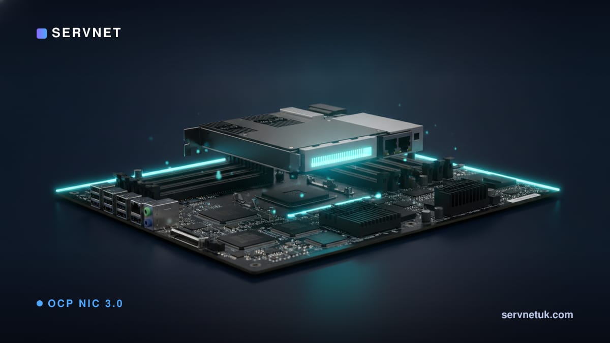
Modern enterprise servers increasingly complement traditional motherboard-integrated Ethernet with dedicated, open-standard mezzanine bays such as OCP NIC 3.0. Governed by the Open Compute Project, whose current specification reached version 1.6.0 on 31 March 2025, this standard introduces high‑density, rear‑serviceable modules as an alternative to legacy PCIe add‑in cards. Unlike standard expansion cards that slot vertically into risers, an OCP NIC 3.0 adapter connects directly to the system board using a specialised board-to-board mezzanine interface. For UK engineering and procurement teams, confusing this mezzanine form factor with traditional PCIe high-performance network cards risks ordering incompatible hardware and halting server commissioning.
View the data behind this chart
| PCIe Base Card | PCIe High Load | OCP 3.0 SFF Cap | |
|---|---|---|---|
| Power Envelope | W67.2 | W86.4 | W80 |
The Architecture Shift: What Is OCP NIC 3.0?
For decades, enterprise rackmount servers relied on two primary methods for network connectivity: fixed onboard network interface controllers (LOM, or LAN-on-Motherboard) and auxiliary PCIe add-in cards (AICs). LOM configurations permanently locked a chassis to specific port counts and physical media—typically dual 1GbE or 10GbE copper ports—leaving organisations unable to upgrade bandwidth as uplinks migrated to 25GbE, 100GbE, or beyond without discarding the motherboard. Conversely, relying exclusively on standard PCIe add-in cards consumed valuable riser slots that could otherwise host storage controllers, accelerators, or coprocessors, while also requiring full chassis cover removal to replace failed network adapters.
The Open Compute Project developed OCP NIC 3.0 as an open, vendor-neutral hardware standard to solve these density, serviceability, and lifecycle bottlenecks. Extending beyond the earlier OCP NIC 2.0 specification, OCP NIC 3.0 defines a dedicated mezzanine slot that server vendors commonly implement as rear‑serviceable through the chassis I/O panel, subject to chassis design. Rather than using the traditional gold-finger edge connector of a PCIe riser slot, an OCP NIC 3.0 card mates to the host via a high-density mezzanine board-to-board (B2B) connector.
This structural shift standardises high-speed I/O delivery across diverse original design manufacturers (ODMs) and tier-one server builders. By decoupling network interfaces from the base motherboard design, infrastructure architects can specify a single chassis platform and dynamically configure it with the exact port types, controllers, and transceivers required for specific bare-metal, virtualised, or cloud workloads. For procurement teams selecting hardware, major vendors offer OCP NIC 3.0 cards across standardized speed and media tiers: dual- or quad-port 10GBASE-T and 10GbE SFP+ for management and legacy networks, dual-port 25GbE SFP28 for mainstream enterprise virtualization, and dual-port 100GbE QSFP28 or 200GbE QSFP56 adapters for high-throughput NVMe-oF storage fabrics and HPC workloads.
Form Factor Mechanics: SFF, LFF, TSFF, and DSFF Variations
While OCP NIC 3.0 originated around two baseline footprints—Small Form Factor (SFF) and Large Form Factor (LFF)—the standard has steadily evolved to accommodate increasingly diverse compute densities across enterprise and hyperscale platforms.
The Small Form Factor (SFF) module is widely used in production deployments and is the focus of most public documentation. With precise dimensions of 76 mm by 115 mm, the SFF card occupies an ultra-compact surface area of 8,740 mm². This constrained profile allows server manufacturers to position the mezzanine bay directly alongside rear power distribution units, storage drives, or riser assemblies without compromising internal cooling channels. Mechanical retention is maintained through vendor‑defined latching mechanisms within the OCP NIC 3.0 mechanical envelope, typically enabling technician servicing from the cold or hot aisle with minimal chassis intrusion.
To address specialised rack enclosures and multi-tier network requirements, the Open Compute Project expanded the mechanical specification with Tall SFF (TSFF) and Dual SFF (DSFF) variants. In practice, enterprise buyers configuring mainstream 1U and 2U rack servers from Dell, HPE, or Lenovo will almost exclusively specify standard SFF modules. By contrast, TSFF is primarily encountered in high-density multi-node compute sleds or SmartNIC deployments that require extra vertical clearance for taller passive heatsinks and layered optical circuitry. DSFF modules cater to specialised multi-controller architectures, housing two discrete controller ASICs within a single rear chassis bay. Understanding how PCIe lanes and slots function provides valuable baseline context when evaluating how these physical footprints route high-speed signals across the motherboard.
Electrical Design: Connectors, Lane Allocation, and Multi-Host Capabilities
The electrical implementation of OCP NIC 3.0 is engineered for high throughput and flexible topology splitting. The specification defines an interconnect scheme using primary and secondary board-to-board connectors capable of delivering up to 32 PCIe lanes to the mezzanine module. In a baseline SFF deployment, the interface typically routes up to x16 PCIe lanes directly from the host processor root complex, supporting bidirectional line rates for high-throughput Ethernet adapters. Modules engage the secondary connector to utilise the full 32 lanes in high-bandwidth dual-controller cards (such as DSFF variants) or multi-host topologies where PCIe bandwidth must be apportioned across independent CPUs or compute sleds.
A standout architectural capability defined in OCP design and implementation frameworks is multi-host topology support. OCP NIC 3.0 adapters can be provisioned in single-host, multi-root, and multi-host environments. In an SFF deployment, a single physical OCP 3.0 card can connect to up to 4 separate hosts simultaneously. Rather than dedicating separate physical NICs, transceivers, and switch ports to four discrete single-socket microservers or compute sleds within a multi-node chassis, a single multi-host OCP 3.0 adapter bifurcates its internal PCIe lanes across each host node.
This architectural flexibility introduces substantial power efficiency and cabling consolidation. In terms of electrical delivery, vendor engineering data shows that an OCP NIC 3.0 SFF module supports up to an 80 W power envelope. While full-height PCIe add-in cards can accommodate higher power draws (standard PCIe card specifications define thresholds such as 67.2 W and 86.4 W, extending higher with auxiliary PCIe power cabling), delivering 80 W within a compact, rear-serviceable form factor without dedicated power leads gives OCP NIC 3.0 sufficient thermal and electrical headroom for dense transceivers and high-performance processing logic.
Advanced Management: Out-of-Band Telemetry and Security Attestation
In most production data centres, network adapters are expected to integrate into the baseboard management controller (BMC) telemetry framework rather than function as isolated data pipes. OCP NIC 3.0 integrates dedicated host-management physical and logical interfaces directly through its primary mezzanine connector pins, bypassing the need for external management cabling or proprietary mezzanine headers.
According to technical implementation specifications, OCP NIC 3.0 host management interfaces natively incorporate RBT (RMII-Based Transport), SMBus (System Management Bus), and PCIe-based sideband channels. These buses allow the chassis BMC to execute out-of-band management tasks—such as inventory polling, link state monitoring, thermal status retrieval, and Network Controller Sideband Interface (NC-SI) traffic forwarding—even when the primary operating system is halted or uninitialised.
Modern enterprise deployments, including those exploring how to understand DPUs and SmartNICs, increasingly rely on cryptographic hardware validation. Vendor support documentation from manufacturers such as Broadcom reveals that OCP NIC 3.0 Ethernet adapter portfolios are catalogued around strict functional attributes. Beyond basic part number, port speed, and I/O media, Broadcom identifies host interface parameters, multihost support, and hardware attestation as core structural attributes. Where supported, attestation capabilities enable the host firmware to cryptographically verify the adapter's identity and firmware integrity before establishing high‑speed PCIe links, safeguarding against supply-chain tampering and unauthorized peripheral installation.
View the data behind this chart
| Layer | Detail |
|---|---|
| Host Management Interfaces | RBT, SMBus, and PCIe host telemetry |
| Physical Mezzanine Layer | Board-to-board primary and secondary interfaces |
| Chassis Form Factors | SFF, LFF, TSFF, and DSFF form definitions |
The UK Procurement Trap: OCP Mezzanine vs PCIe Add-In Cards
In the UK corporate, colocation, and public-sector markets, network card procurement continues to suffer from a recurrent, highly disruptive specification error. IT procurement teams upgrading compute nodes frequently order standard PCIe add-in cards while specifying base server chassis that feature an unpopulated OCP NIC 3.0 mezzanine bay.
Because enterprise systems like Dell PowerEdge, Lenovo ThinkSystem, and HPE ProLiant often offer an OCP 3.0 slot that can be designated as a primary network port, selecting an add-in card leaves the primary mezzanine slot dead. A standard PCIe NIC cannot physically or electrically mate with an OCP 3.0 bay. The OCP slot requires a low-profile mezzanine card with a board-to-board connector, secured through the rear chassis bulkhead, whereas a standard NIC requires a PCIe riser slot and standard expansion bracket.
When an engineer unboxes a server in a London, Manchester, or Slough colocation facility only to discover a bare OCP blanking plate and an incompatible PCIe card, the deployment stalls immediately. Because enterprise OCP NIC modules must be sourced through approved IT channel distributors, replacement lead times can introduce costly project delays. A misordered network adapter can create operational downtime expenses that may exceed the price of the module itself. IT teams configuring new deployments via tools such as an HPE server configurator must systematically verify whether networking is mapped to an OCP 3.0 mezzanine module or a riser-based PCIe slot before placing purchase orders.
Operational Maintenance and Troubleshooting Best Practices
Deploying OCP NIC 3.0 modules delivers clear operational advantages for enterprise infrastructure teams, particularly in terms of mean time to repair (MTTR) and mechanical airflow management. Because standard PCIe expansion cards mount perpendicularly or parallel to the motherboard on secondary risers, replacing a failed adapter traditionally requires powering down the node, pulling the chassis out of the rack onto server rails, removing the top chassis cover, and dismantling the riser assembly. In high-density 1U server environments, this process disrupts adjacent cabling and interrupts system cooling.
In contrast, OCP NIC 3.0 modules are typically designed for rear accessibility, depending on the chassis implementation. In many OCP NIC 3.0 chassis designs, technicians can release a mechanical retention mechanism at the rear I/O panel and slide the module out horizontally. System air baffles and internal PCIe risers remain completely undisturbed, preserving internal airflow channels and preventing cable strain.
To avoid common field issues, data centre operations teams should adhere to three baseline practices during installation and lifecycle management:
Verify mechanical bracket alignment: Ensure the OCP 3.0 card matches the chassis latching style (ejector latch, internal lock screw, or pull-tab). Forcing an mismatched card into an OCP bay risks bending the delicate high-density pins on the motherboard's board-to-board connector.
Validate BMC sideband routing: When configuring out-of-band management via NC-SI over RBT or SMBus, confirm in system BIOS/UEFI that the OCP mezzanine slot is designated as the active shared management port.
Cross-reference multi-host bifurcation: In multi-node enclosures, verify that the motherboard firmware correctly splits the 16 or 32 PCIe lanes across the compute nodes. If lane bifurcation is misconfigured, secondary hosts will fail to detect their allocated network interfaces during boot.
Sources
Every figure in this article traces to the sources below.
- •Open Compute Project — Server/NIC Specification 1.6.0 & Mechanical Drawings
- •NVIDIA — OCP NIC 3.0 Adapter Cards Architecture Brochure
- •Open Compute Project — OCP NIC 3.0 Design and Implementation Experiences
- •Broadcom — OCP NIC 3.0 Ethernet Adapter Family Support Documentation