

Thermal Design Power (TDP) is the maximum continuous heat, measured in watts, that a server CPU's cooling system must dissipate under sustained reference workloads. It is an engineering target for cooling solutions rather than a hard ceiling on instantaneous electrical draw from the socket or wall. Yet in enterprise procurement, TDP remains one of the most routinely misunderstood metrics. With current flagship server processors spanning thermal envelopes from 330W up to 500W, budgeting data centre circuits and uninterruptible power systems based purely on these nameplate figures risks transient throttling, breaker trips, or severe under-provisioning. Translating TDP into operational realities requires understanding configurable envelopes, turbo headroom, and platform delivery overheads across modern compute fabrics.
View the data behind this chart
| EPYC 9755 | Xeon 6980E+ | EPYC 9655P | Xeon 6960E+ | EPYC 9455 | EPYC 7763 | |
|---|---|---|---|---|---|---|
| Default TDP | W500 | W400 | W400 | W330 | W300 | W280 |
What Is CPU TDP? The Core Definition and Why It Is Misunderstood
Thermal Design Power (TDP) designates the maximum continuous heat dissipation that a cooling solution must be able to reject under specified reference workloads, typically corresponding to sustained operation at standard (non‑overclocked) conditions rather than peak turbo states. In enterprise system design, the fundamental misconception is equating TDP with the total electrical wattage drawn at the wall plug or even at the socket pins. TDP was conceived primarily as a thermodynamic sizing parameter for thermal engineers designing heatsinks, vapor chambers, fans, and liquid cooling loops, rather than as a direct wall‑power measurement.
Crucially, modern server processors are dynamic, multi-core thermodynamic systems governed by autonomous embedded telemetry. A processor's real-time electrical draw is governed by dynamic voltage and frequency scaling, which continually samples thermal headroom, current delivery, and workload concurrency. While some vendor glossaries describe TDP as a power or heat ceiling that should not be exceeded, in practical server design TDP is best treated primarily as a thermal design target and not as a guarantee of maximum instantaneous package or wall power. When a system administrator views an advertised server processor rating, it does not guarantee an idle or steady-state wall draw, but rather establishes an engineering baseline for continuous heat extraction.
- •TDP is an engineering target for heatsink and cooling design, not a wall-power measurement.
- •Dynamic voltage and frequency scaling allows processors to adjust wattage continuously based on socket limits and execution demand.
- •Relying on TDP alone as an electrical power budget can lead to under‑sizing of power delivery units and rack infrastructure, especially with modern high‑core, high‑TDP processors.
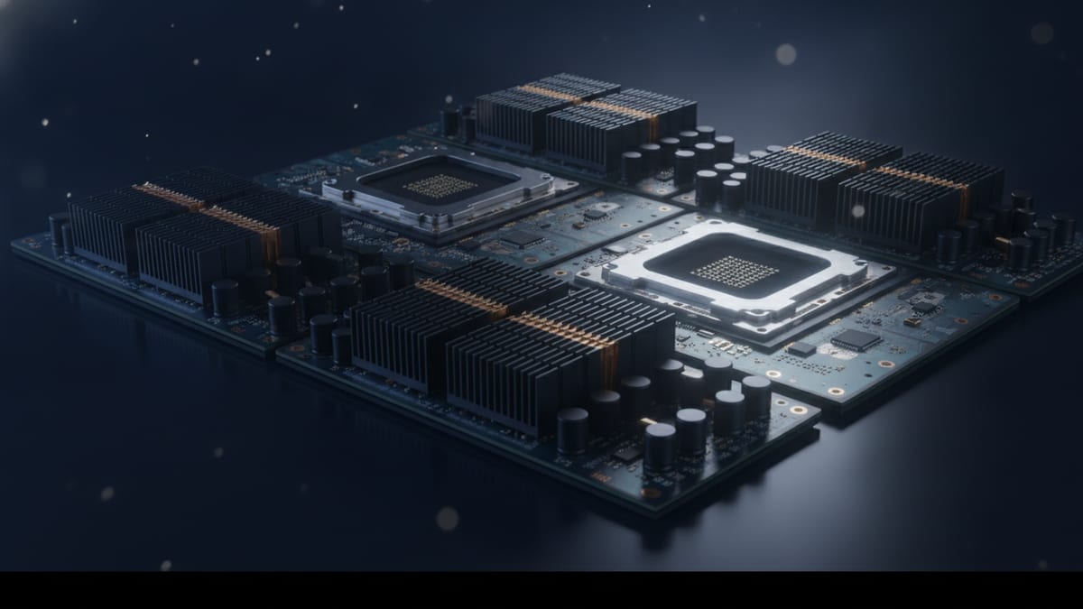
TDP vs Actual Power Consumption: Unpacking Socket Envelopes and Real Draw
The gap between nominal TDP and real-world electrical consumption stems from the architectural divergence between sustained thermal dissipation and transient electrical draw. Under intensive instruction sets or parallel multi‑threaded spikes, instantaneous package power can escalate to levels at or above the advertised TDP or base power rating, depending on how boost and power limits are configured for a given SKU. To comprehend this behaviour, IT planners must distinguish between continuous thermal dissipation—which dissipates through heatsinks over seconds and minutes—and instantaneous transient electrical power, which places microsecond-level demands on the motherboard Voltage Regulator Modules (VRMs) and Power Supply Units (PSUs).
A clear demonstration of how dynamic boost mechanisms operate relative to baseline ratings can be observed across processor architectures publishing distinct power tiers. Intel compare-sheet data demonstrates this operational delta clearly on client‑class parts: a processor with a 65W processor base power is rated alongside a 117W maximum turbo power, illustrating how turbo draw can exceed a baseline figure. While this comparison reflects baseline client/edge architectures rather than high-density rack silicon, it illustrates the exact engineering mechanic governing turbo execution. When cores accelerate into boost states, instantaneous power escalates substantially above the baseline target until thermal or algorithmic thresholds enforce throttling back toward nominal design limits.
- •Processor Base Power defines sustained operation under reference workloads at base clock speeds.
- •Maximum Turbo Power accounts for opportunistic boosting, where power draw temporarily surges above nominal TDP baselines.
- •Motherboard VRMs and server PSUs must absorb millisecond‑scale electrical spikes that may exceed the levels implied by steady‑state thermal dissipation envelopes.
Intel Base and Turbo Power vs AMD Configurable TDP Metrics
Across modern server platforms, vendors manage thermal headroom and power distribution through distinctly named architectural parameters. Server buyers evaluating enterprise hardware must look closely at how Intel and AMD define power ranges across spec sheets.
Intel's current generation of enterprise processors highlights the scaling of high-density silicon. According to Intel’s ARK product tables for the Xeon 6900E+ family, current entries include the Xeon 6960E+ at a 330W TDP with 144 cores, and the Xeon 6970E+ and 6980E+ at 400W TDP with 192 and 264 cores respectively, each listed with a 3.2 GHz max turbo frequency and Q2 2026 launch dates. These figures show that, for Intel’s current Xeon 6900E+ family, top‑end server CPUs sit in roughly the 330W to 400W TDP class, where cooling architectures must be engineered to handle heavy sustained heat rejection under full AVX and dense compute execution.
Conversely, AMD addresses power envelope management within its EPYC platform through default TDP and Configurable TDP (cTDP). The EPYC 9005 family illustrates this spectrum clearly. At the high end of AMD’s current EPYC 9005 family sits the EPYC 9755, featuring a default TDP of 500W and a cTDP range of 450W to 500W—one of the highest‑power mainstream server CPUs publicly specified by AMD. In contrast, the AMD EPYC 9655P carries a default TDP of 400W with a cTDP range from 320W to 400W, matching the 400W default TDP and 320W-400W cTDP of the EPYC 9745, which delivers a boost clock up to 3.7 GHz and an all-core boost of 3.45 GHz. Within the same generation, AMD's EPYC 9455 scales down to a 300W default TDP with a 240W-300W cTDP band. It is important to note that cTDP represents a vendor-defined configuration range rather than a direct guarantee of actual wall power draw; cTDP is not the same as measured wall power, and thermal and performance behavior depend on how platform limits, boost frequencies, and workloads interact.
This architectural configurability extends into specialised enterprise segments. The AMD EPYC 8534P and EPYC 8434P each specify a 200W default TDP with a wide cTDP range of 155W to 225W. This identical envelope is mirrored in the AMD EPYC Embedded 8534P (200W TDP, 155W‑225W cTDP), illustrating that at least some embedded/server‑class parts retain configurable thermal envelopes. Meanwhile, earlier-generation or specialised processors exhibit tighter boundaries: the AMD EPYC 7443P operates at a 200W default TDP with a narrower 165W-200W cTDP range, while the AMD EPYC 7763 sits at a fixed 280W default TDP. When sizing platforms, engineers can understand server BIOS power and performance profiles to ensure socket parameters align directly with facility delivery capabilities.
Cascading Platform Power: From Socket Watts to Rack Cooling
Procuring server hardware requires mapping socket TDP to the broader platform and rack ecosystem. A dual-socket enterprise node configured with two flagship processors represents a substantial default thermal load across the silicon alone. However, package power is merely one component of the server's aggregate electrical draw. Every secondary component draws power directly from the 12V plane: high-speed multi-channel DDR5 registered ECC memory arrays, NVMe enterprise solid-state drives, high-throughput network interface cards (NICs), and dense arrays of counter-rotating chassis fans.
Furthermore, power supply conversion efficiency introduces overhead. Operating at typical PSU conversion efficiencies, a server drawing around 1,400W of internal DC power will draw additional input power from the facility distribution circuit to cover conversion losses. These aggregate loads directly dictate cabinet heat rejection requirements. To maintain optimal thermal envelopes without entering catastrophic emergency throttling, facility planners must determine your server room cooling needs based on total heat output rather than baseline processor TDP. In dense configurations, unmodelled platform draw will rapidly deplete computer room air handler (CRAH) capacity.
- •Dual-socket configurations hosting flagship processors demand upwards of 1kW solely for processor silicon.
- •Chassis fans, memory, storage backplanes, and peripheral cards add several hundred watts of overhead to baseline CPU draws.
- •Power supply transformation inefficiencies convert additional input power directly into rejected cabinet heat.
Engineering PSU Sizing and Thermal Delivery for High-TDP Nodes
Determining power supply unit (PSU) capacity and facility power circuits cannot be achieved by summing processor default TDPs. Instead, system engineers must design around the worst-case combined transient envelope. When multiple high-core processors transition concurrently into peak boost states—such as an Intel Xeon 6980E+ boosting all 264 cores toward its 3.2 GHz ceiling, or an EPYC 9745 sustaining an all-core boost of 3.45 GHz—the instantaneous draw creates steep current ramp rates.
System integrators configuring multi-node chassis or enterprise compute clusters must deploy redundant PSUs (such as 1+1 or 2+2 configurations) rated to absorb maximum transient peaks without crossing tripping thresholds or dropping into sub-optimal conversion efficiency bands. Engineers can calculate watts, amps, and VA to map exact circuit loading and phase distribution across redundant three-phase rack distribution units. Sizing exclusively to default TDP leaves little margin for burst execution and can contribute to risks such as unexpected hardware reboots, accelerated component wear, and reduced VRM lifetime under prolonged stress.
View the data behind this chart
| Model | Default TDP | Configurable TDP (cTDP) | |
|---|---|---|---|
| AMD EPYC 9755 | AMD EPYC 9755 | 500 W | 450 W-500 W |
| Intel Xeon 6980E+ | Intel Xeon 6980E+ | 400 W | Fixed Base (3.2 GHz Max) |
| AMD EPYC 9655P | AMD EPYC 9655P | 400 W | 320 W-400 W |
| Intel Xeon 6960E+ | Intel Xeon 6960E+ | 330 W | Fixed Base (3.2 GHz Max) |
| AMD EPYC 9455 | AMD EPYC 9455 | 300 W | 240 W-300 W |
| AMD EPYC 8534P | AMD EPYC 8534P | 200 W | 155 W-225 W |
| AMD EPYC 7443P | AMD EPYC 7443P | 200 W | 165 W-200 W |
UK Data Centre Implications: Density, Metering and Infrastructure Budgeting
For UK infrastructure architects and colocation customers, managing server CPU TDP is intrinsically tied to facility commercials and capacity allocations. Many UK colocation providers, particularly in major connectivity hubs such as Slough, Docklands, and Manchester, contract rack space around provisioned kilowatt thresholds per cabinet; common offerings for standard air‑cooled footprints are in the roughly 5kW to 15kW range, with specialised high‑density halls provisioned for higher bands.
Deploying nodes populated with contemporary high-TDP hardware shifts rack thermodynamics dramatically. As a firm rule of thumb, infrastructure planners should assume a 25% to 30% electrical overhead above aggregate CPU TDP figures when sizing deployments against contracted rack limits. In standard UK colocation allocations of 5kW to 15kW, this platform margin quickly caps usable cabinet density. For instance, a dual-socket server housing high-wattage processors will typically draw 1.3kW to 1.5kW at the rack PDU once memory arrays, storage, fan arrays, and PSU losses are factored in, meaning a contracted 10kW allocation is fully committed by only six or seven dual-socket chassis. Attempting to fit higher server densities without explicitly provisioning high-density cooling and power infrastructure risks tripping circuit breakers and incurring out-of-contract billing surcharges. Facilities teams must learn more about rack power density to avert local hot-spot creation and maintain compliance with contracted power thresholds.
- •UK colocation contracts strictly enforce kW-per-rack allocation limits; exceeding contracted draw incurs severe commercial penalties.
- •High-density nodes populated with top-tier processors rapidly consume standard 5kW-15kW rack envelopes with only a handful of chassis.
- •Accurate thermal budgeting dictates whether a facility can support air-cooling solutions or requires liquid-to-chip infrastructure.
Procurement Checklist: Reading Server Spec Sheets Accurately
To safeguard capital investments and ensure operational reliability across 2026 infrastructure deployments, technical buyers must systematically evaluate vendor documentation beyond headline marketing figures. A robust server deployment strategy necessitates auditing base, boost, and platform-level parameters before issuing hardware tenders.
When evaluating processor candidates across enterprise catalogues, infrastructure teams should execute a four-point architectural audit: verify baseline TDP against configurable cTDP boundaries; identify peak all-core and single-core boost clock profiles; calculate total system power factoring auxiliary component dissipation; and ensure the chassis cooling solution is validated to dissipate maximum sustained boost loads without thermal throttling.
- •Audit Default TDP and cTDP: Determine whether the platform will run at default nominal wattage or be tuned down within its configurable envelope.
- •Inspect Turbo and Boost Headroom: Map maximum clock targets against platform thermal limits to evaluate transient power headroom.
- •Model Platform and VRM Overhead: Add memory, NVMe, and PCIe power draws to socket ratings when sizing server chassis power supplies.
- •Validate Facility Delivery: Confirm UK rack PDU breaker ratings and cooling infrastructure align with peak server electrical draws rather than base nominal values.
Sources
Every figure in this article traces to the sources below.
- •Intel — Xeon 6900E+ Series Processor Specifications and Launch Dates
- •AMD — EPYC 9005 Series Server Processor Specifications (EPYC 9755, 9655P, 9745, 9455)
- •AMD — EPYC 8004 and 7003 Series Specifications (EPYC 8534P, 8434P, 7443P, 7763)
- •TechPowerUp — AMD EPYC Embedded 8534P Thermal Envelope Specifications
- •Intel — Processor Base Power vs Maximum Turbo Power Comparison
View the data behind this chart
| Layer | Detail |
|---|---|
| Transient Socket Turbo Spikes | Draw above TDP during dynamic boost states |
| Advertised Base TDP Rating | Continuous thermal dissipation target (e.g. 330W-500W flagship CPUs) |
| Chassis Platform Component Overhead | Memory arrays, NVMe storage, fans, and NIC draw |
| Facility Circuit and Redundant PSUs | Sized for total rack electrical loads and conversion |