
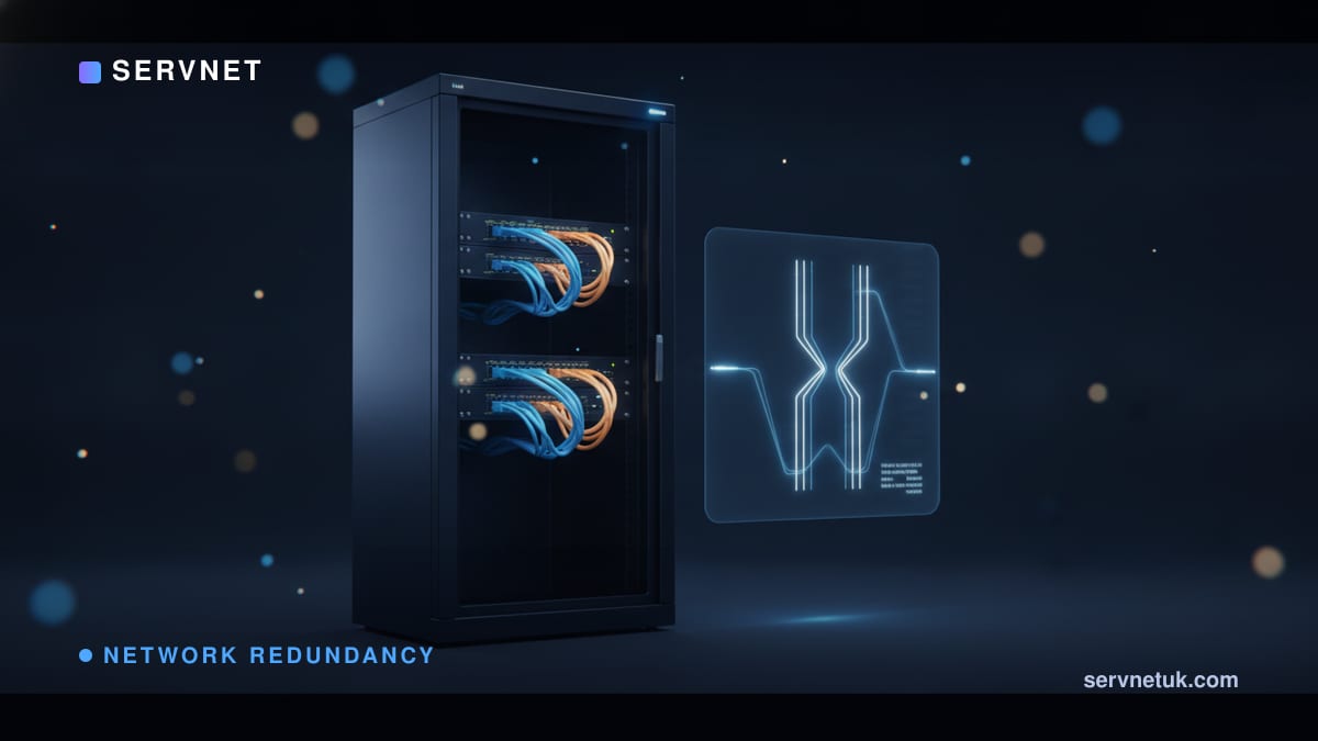
Network redundancy fails most often when engineers conflate Layer 2 link aggregation with Layer 3 default gateway resilience. True high availability requires isolating failure domains across hardware, switching and routing layers. Cisco documentation highlights that while a switch stack operates multiple physical switches as a single logical system with unified management and control-plane behaviour, a stack does not automatically remove every failure domain. A shared stack-ring, common software state or joint management dependency can impact all members simultaneously. In contrast, multi-chassis link aggregation (MLAG) maintains independent switch chassis and control planes while presenting a unified link bundle to downstream nodes. Above both, Virtual Router Redundancy Protocol (VRRP) and Hot Standby Router Protocol (HSRP) isolate first-hop routing failures. Understanding how these layers interact across Layer 2 and Layer 3 switches ensures resilient UK enterprise deployments—note that convergence times, command syntax and specific parameter limits are platform- and software-dependent, so always confirm exact specifications against vendor documentation.
View the data behind this chart
| Layer | Detail |
|---|---|
| Layer 3 Default Gateway | VRRP or HSRP virtual router IP across two or more physical routing devices |
| Layer 2 Multi-Chassis Switching | MLAG dual-chassis link bundle or switch stack with loop prevention |
| Physical Uplinks and Cable Paths | Dual uplinks with spanning-tree loop control or link aggregation |
| Power Supply and Feed Resilience | Dual power supply units protecting against single PSU or feed loss |
Redundancy is an architectural stack, not a single feature
Network resilience cannot be achieved by purchasing a single resilient box. In enterprise infrastructure, genuine redundancy requires mapping specific network mechanisms directly to the precise physical or logical fault each mechanism is built to survive. Dual PSUs can protect against one PSU or feed failure when supplied by independent, correctly designed power paths, but they provide zero protection if an administrative command corrupts a switch configuration. Similarly, running dual uplinks protects against an accidental cable sever, but without a loop-control mechanism, redundant links can create catastrophic forwarding loops.
A robust design maps every tier of the network to its corresponding failure domain. At the physical layer, dual power supply units (PSUs) cover one PSU or feed failure. At the access and distribution layer, dual uplinks cover one cable or port path, while switch stacking and multi-chassis link aggregation (MLAG) cover selected switch failures. At the first-hop routing layer, gateway redundancy protocols (VRRP and HSRP) cover the loss of the active default gateway. Spanning tree remains active across the topology to prevent Layer 2 loops where redundant physical cabling exists.
Attempting to solve all failure modes with a single protocol or technology introduces architectural blind spots. An engineer who relies on switch stacking to provide high availability across an entire server room may overlook default gateway failover or common-cause software crashes. By dissecting resilience into hardware, link, chassis and routing layers, network architects can systematically isolate single points of failure.
Switch stacking: consolidated control plane and blast radius
Switch stacking binds multiple physical switches into a single logical entity managed with consolidated control and administration. Downstream servers or edge switches perceive the stack as one logical switch chassis, allowing network interfaces on separate physical stack members to combine into link aggregation groups. This architecture simplifies initial deployment and eliminates the need to configure separate routing protocols across peer switches.
However, consolidating the control plane concentrates operational risk. Operating multiple physical switches as a single logical system consolidates management and control-plane behaviours. Consequently, a stack does not automatically remove every failure domain: a stack-ring failure, backplane fault or common software crash can disable all members simultaneously, making physical rack separation and power diversity vital.
Physical placement and electrical diversity remain essential requirements when deploying stacked switches. Stacking members placed in the same equipment rack and connected to a common power distribution unit remain vulnerable to rack-level electrical faults. Distributing stack members across separate racks and power circuits prevents a localized physical fault from taking down the entire logical switch.
MLAG: dual chassis with independent control planes
Multi-chassis Link Aggregation (MLAG)—and vendor-specific implementations like Cisco Virtual Port Channel (vPC)—approaches local network resilience from an opposing architectural philosophy. Instead of merging two switches into a single logical brain, MLAG preserves two independent switches, each maintaining its own control plane, routing engine, and management instance. MLAG peers use vendor-defined peer links and, where applicable, keepalive or dual-active detection mechanisms to coordinate forwarding and link-aggregation state.
This dual-chassis separation enables downstream devices, such as virtualisation hypervisors, storage arrays, or firewalls, to form a single logical link bundle connected across two distinct physical chassis. MLAG allows downstream nodes to establish an active-active LACP bundle across both chassis simultaneously. If one chassis fails, the surviving peer continues forwarding active traffic across the remaining member links with minimal sub-second convergence delay.
The clear operational benefit of MLAG is the complete isolation of switch control planes, preventing control-plane memory exhaustion or software crashes from propagating between peers. If dedicated peer links are severed, MLAG implementations invoke split-brain protection—such as out-of-band peer-keepalive links or dual-active detection—to disable downstream ports on the designated secondary peer and prevent dual-active forwarding loops.
Maintenance windows and firmware lifecycle realities
The control-plane differences between switch stacking and MLAG become acutely evident during operating system maintenance and security patching. Stack upgrades generally require coordinated member reloads that cause brief traffic interruptions. Because shared software state and stack-ring master re-elections disrupt active traffic forwarding, enterprise teams routinely restrict stack upgrades to out-of-hours maintenance windows.
In contrast, MLAG platforms support rolling upgrades. Because each switch runs an independent operating system instance and control plane, an engineer can isolate one chassis, apply updates, reboot, and verify forwarding stability before repeating the process on the peer, maintaining network availability throughout the maintenance cycle.
This operational divergence directly dictates maintenance strategy and service-level agreements. Continuous-uptime environments favour MLAG specifically to avoid stack-wide reboots during patching cycles. Organisations balancing these architectural options alongside third-party network maintenance can weigh the operational cost of scheduled stack downtime against the initial configuration overhead of multi-chassis peering.
Default gateway redundancy: VRRP and HSRP mechanics
Neither switch stacking nor MLAG eliminates the need for first-hop default gateway redundancy. While stacking and MLAG solve Layer 2 switch and link availability, end-user client devices and servers require a dependable Layer 3 default gateway address to route traffic off their local subnet. If a distribution switch acting as the default gateway experiences a routing failure, downstream hosts lose off-subnet connectivity even if their physical switch links remain up.
Virtual Router Redundancy Protocol (VRRP) is an IETF open-standard election protocol designed to solve this problem. Under VRRP, a group of routers forms one virtual router, electing one router as primary while the others act as backups. LAN clients configure the shared virtual IP address as their default gateway, avoiding client reconfigurations during gateway failover. In the cited Cisco ASR implementation, backup-router priority is configurable from 1 through 254 to influence which router takes over if the primary fails.
Hot Standby Router Protocol (HSRP) is Cisco's protocol performing the same first-hop redundancy function. HSRP groups contain two or more routers providing hot-standby service, using priority elections to select the active forwarder. Configuring multiple HSRP groups with alternating priorities allows different VLANs to share load across distinct gateways. On Cisco blade switches, HSRP supports up to 32 VLAN or routing interfaces, and HSRP and VRRP cannot run concurrently on the same interface.
View the data behind this chart
| Scope & Mechanism | VRRP Protocol | HSRP Protocol | |
|---|---|---|---|
| Specification standard | IETF open standard | Cisco proprietary | Vendor interoperability |
| Group router membership | 1 primary plus backups | 2 or more routers | Both provide virtual IP |
| Configurable priority | 1 to 254 in cited ASR | Priority election scheme | Highest priority active |
| Supported interfaces | Ethernet and bundles | Up to 32 on cited switch | Per-VLAN or routing links |
| Concurrent protocol use | Not co-run on same port | Not co-run on same port | Mutually exclusive in cited |
Dual uplinks, link bundles, and spanning tree loop control
Connecting access switches to distribution switches via dual physical uplinks is standard practice, but unmanaged redundant cabling creates Layer-2 loops. Broadcast packets circulating endlessly across redundant Layer-2 paths cause broadcast storms. STP or an equivalent loop-control mechanism prevents Layer-2 loops; depending on the design, it may block some paths while link aggregation can use multiple paths actively.
Spanning Tree and gateway redundancy solve different problems: spanning tree controls Layer-2 topology, while VRRP or HSRP supplies a resilient Layer-3 default gateway. In a simple two-link STP topology, one link may be unused for a given VLAN, reducing available capacity; quantify the effect for the actual topology rather than assuming bandwidth is universally halved.
MLAG and stacking allow downstream devices to form active-active LACP bundles across chassis, eliminating reliance on a single access switch. On Cisco ASR routing platforms, VRRP supports Ethernet interfaces, Ethernet subinterfaces and Ethernet link bundles. Spanning tree remains active across the topology to prevent forwarding loops where redundant physical cabling exists.
Specifying resilience by failure domain in UK infrastructure
When architecting resilient UK campus and datacentre networks, specify redundancy by failure domain rather than by product label. A robust technical specification explicitly maps each infrastructure component to the exact fault it survives: dual PSUs cover power supply or circuit loss, dual uplinks cover cable or transceiver failure, switch stacking or MLAG covers chassis failure (with peers physically separated across racks), and VRRP or HSRP covers the default gateway.
Validating network resilience requires testing each failure domain against its expected behaviour: verify feed resilience by disconnecting one power path; test cable/port failure by pulling active uplink connections; validate switch failure behaviour by powering off an MLAG or stack member; test peer-link loss and split-brain detection; confirm gateway election by shutting down the active VRRP or HSRP router; and execute staging software upgrades to measure actual convergence times.
In UK deployments, physical redundancy must account for regional utility and carrier realities. Specifying dual switch power supplies provides little protection if both feeds originate from the same building intake or local Distribution Network Operator (DNO) transformer; genuine feed resilience requires dual low-voltage panel feeds or an on-site generator with automatic transfer switching. Similarly, WAN edge resilience requires diverse Openreach fibre routes using separate exchange handoffs or pairing an Openreach leased line with an independent altnet provider, ensuring physical duct work or street-cabinet incidents cannot disrupt both circuits.
Commercial lifecycle management must align with these technical domains. Where mission-critical campus hardware reaches vendor end-of-sale—such as the Cisco IE 5000 series reaching end-of-support on 31 July 2029—evaluating a Cisco SmartNet alternative allows organisations to maintain break-fix coverage. Evaluating single-vendor vs multi-vendor networks helps UK procurement teams determine whether open standards like VRRP provide superior long-term hardware flexibility over proprietary clustering protocols.
Sources
Every figure in this article traces to the sources below.
- •Cisco — Catalyst 2960-XR HSRP and VRRP Configuration Guide
- •Cisco — Nexus 9000 Series Unicast Routing Configuration Guide
- •Cisco — ASR 9000 Series IP Addresses Configuration Guide
- •Cisco — Catalyst Blade Switch 3110 Configuration Guide