

Navigating the transition from traditional 2.5-inch enterprise storage to next-generation server architectures hinges on understanding the critical divide between U.2 vs U.3 interfaces and emerging EDSFF alternatives. While U.2 and U.3 share the physical SFF-8639 connector, compatibility depends on whether the server's backplane and controller implement the SFF-TA-1001 tri-mode design, meaning native U.2 backplanes may not detect U.3 drives. Concurrently, SNIA describes EDSFF E3—governed by the SFF-TA-1008 specification and SFF-TA-1002 connector—as the main intended successor to the traditional U.2 2.5-inch form factor in 1U and 2U servers, scaling from 25W up to 40W (and 70W across the wider E3 family). As UK organisations balance existing chassis with modern deployments, matching drive pinouts to backplane wiring is vital.
View the data behind this chart
| Intel 3.84TB U.2 | Kioxia 3.2TB E3.S | Kioxia 6.4TB E3.S | Kioxia 15.3TB U.2 | Memblaze 7.68TB | |
|---|---|---|---|---|---|
| UK List Price | £519.98 | £664.74 | £1138.05 | £1912.49 | £2950 |
The Enterprise SSD Landscape: U.2, U.3, and the Shift to EDSFF
In mid‑2026, enterprise server storage largely spans two dominant SSD form‑factor generations: legacy 2.5‑inch bays (U.2/U.3) and newer EDSFF designs such as E1.S and E3.S. On the other side sits the Enterprise and Datacenter Standard Form Factor (EDSFF) family, primarily comprising E1.S and E3.S. For years, IT teams treated the 2.5-inch bay as an interchangeable standard, but the coexistence of distinct pinout implementations and new form factors has complicated routine drive replacement and expansion.
The primary tension today centres on backplane interoperability. U.2 remains widespread across existing server estates as the traditional 2.5-inch NVMe standard. However, system vendors increasingly deploy U.3 backplanes to consolidate NVMe, SAS, and SATA interfaces onto a unified chassis footprint. Meanwhile, SNIA form‑factor guidance states that EDSFF E3 is intended to update and replace the traditional U.2 2.5‑inch form factor in servers and storage systems, providing a standardised path for modern enterprise workloads.
Understanding this landscape requires separating physical drive dimensions from electrical signal definitions. An engineering team evaluating whether to buy legacy 2.5-inch drives or commit to EDSFF must evaluate physical slot dimensions, backplane routing, and controller compatibility before issuing a purchase order.
- •U.2: The 2.5‑inch NVMe form factor utilising the SFF‑8639 connector pinout, widely deployed in existing enterprise servers.
- •U.3: A unified link definition (SFF-TA-1001) that multiplexes NVMe, SAS, and SATA over the SFF-8639 connector using tri-mode controllers (detailed below).
- •EDSFF E1.S: A narrow 1U-focused drive family measuring 31.5 mm by 111.49 mm designed for high-density chassis.
- •EDSFF E3.S: The 3U Short form factor measuring 76 mm by 112.75 mm, engineered to replace U.2 in mainline 1U and 2U servers.
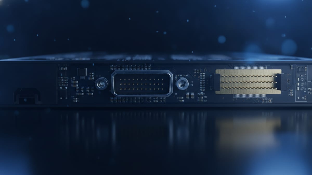
U.2 vs U.3: Decoding Connector Architecture and the Compatibility Trap
The core distinction in the u.2 vs u.3 comparison lies within signal routing rather than drive exterior dimensions. Both standards rely on the physical SFF-8639 connector. However, SNIA describes U.3 as conforming to the SFF-TA-1001 link definition. Under SFF-TA-1001, the high-speed differential pins are reassigned so that a single backplane receptacle can detect and route native PCI Express (PCIe) lanes for NVMe, or legacy SAS and SATA lanes.
This shared connector creates the notorious 'U.2/U.3 backplane trap' that catches procurement managers and datacentre technicians. A drive labelled U.3 is not universally plug-and-play across legacy U.2 backplanes. According to SNIA documentation, U.3 operation is fundamentally tied to tri-mode HBAs or RAID controllers and properly enabled system backplanes. If an enterprise installs a modern U.3 SSD into a purely native U.2 backplane lacking tri-mode routing logic or auto-sensing switches, the host system will often fail to link train with the drive or fail to recognise it altogether.
Backward compatibility is defined in the specifications, with U.3 drives generally designed to operate in U.2 hosts. However, installing a U.2 drive into a U.3-only bay will typically result in non-detection due to differing pin assignments and signaling requirements. Organisations planning drive swaps must verify their system backplane wiring and controller specifications rather than assuming physical fit ensures electrical negotiation, especially when moving older U.2 drives into newer U.3-enabled systems.
EDSFF E3.S: Architecture and Specifications of the U.2 Successor
Recognising the physical and thermal limitations of the legacy 2.5-inch envelope, SNIA and the enterprise storage industry introduced the EDSFF family. Within this family, EDSFF E3.S is positioned by SNIA and major vendors as the main successor to U.2/U.3 in enterprise servers. Solidigm’s technical documentation notes that E3.S stands for EDSFF 3U Short and is specifically intended to replace the U.2 2.5-inch form factor.
The physical and electrical design of E3.S deviates completely from the SFF-8639 legacy standard. According to Kioxia technical specifications, E3.S drives measure 76 mm in width, 112.75 mm in length, and 7.5 mm in thickness. The E3 standard is defined by the SFF-TA-1008 mechanical and electrical specification, discarding the pin-heavy SFF-8639 connector in favour of the high-density SFF-TA-1002 card-edge connector.
SNIA form-factor documentation clarifies that the broader E3 family maintains a consistent height of 76 mm across its implementations, offering standard lengths of 112.75 mm (Short) and 142.2 mm (Long), alongside thickness profiles of 7.5 mm and 16.8 mm. This geometry allows system designers to optimise airflow paths across the drive body, eliminating the bulky drive sleds and restrictive metal bay enclosures associated with traditional 2.5-inch enterprise SSDs.
E1.S vs E3.S: Distinct Roles Across EDSFF Server Architectures
While E3.S targets the replacement of mainline enterprise 2.5-inch bays, EDSFF also provides the E1 family. Kioxia product documentation identifies the EDSFF E1 family as a distinct form factor line featuring thickness variants and its own specification set. SNIA specifications list standard E1.S dimensions at 31.5 mm in width and 111.49 mm in length, making it significantly narrower than the 76 mm profile of E3.S.
Because of these dimensional differences, E1.S drives are tailored for dense, horizontally or vertically stacked 1U hyperscale nodes, whereas E3.S is built for traditional enterprise 1U and 2U chassis. However, interoperability questions often arise regarding whether E1 drives can function within E3 server slots. SNIA guidance notes that while a single E1.S drive is electrically compatible with an E3 slot, a custom PCB or dedicated carrier card is required to bridge the physical slot difference.
Enterprise buyers must therefore avoid conflating E1.S and E3.S during infrastructure procurement. Selecting E1.S requires dedicated chassis bays engineered for the 31.5 mm standard. Conversely, enterprise storage arrays and general-purpose servers migrating away from U.2 standardise on E3.S to leverage its wider thermal surface and mechanical alignment with standard 1U and 2U front panels.
Thermal Design, Power Draw, and PCIe Gen5 Operations
The shift from U.2/U.3 to EDSFF is heavily motivated by power delivery and thermal dynamics under PCIe 5.0 workloads. High-speed enterprise SSD controllers operating across Gen5 interfaces generate substantial heat across dense read/write operations. In older 2.5-inch enclosures, cooling components within a 15 mm chassis requires aggressive fan speeds and creates hot spots across the backplane.
EDSFF solves this via revised connector layouts and native heatsink integration. Sourced from Kioxia and SNIA technical publications, 7.5mm E3.S variants are rated up to 25W, while 16.8mm variants scale up to 40W, and the broader E3 family supports devices up to 70W for applications like CXL or accelerators. E1.S is engineered with lower power profiles suited for constrained environments. The SFF‑TA‑1002 card‑edge connector is designed to support PCIe Gen5 data rates and thermal layouts more effectively than the older SFF‑8639‑based 2.5‑inch bays.
To manage sustained high-throughput workloads efficiently, modern enterprise storage deployments require careful balancing of IOPS, bandwidth, and chassis thermal dissipation. IT engineers can convert IOPS and throughput for performance analysis across differing bus generations to calculate the impact of PCIe 5.0 drives operating near their 25 W threshold. Managing these thermal boundaries ensures that Gen5 storage media maintain maximum throughput without triggering thermal throttling.
View the data behind this chart
| Layer | Detail |
|---|---|
| EDSFF Native Infrastructure | Direct SFF-TA-1002 connector routing for E3.S |
| Tri-Mode Enabled Backplane | SFF-TA-1001 links supporting U.2 and U.3 drives |
| Legacy U.2 NVMe Backplane | SFF-8639 connector requiring native U.2 drives |
Backplane Compatibility Matrix and Migration Strategies
Migrating an enterprise storage tier requires understanding what can physically plug into a given slot and whether the host controller will communicate with it. The rules governing U.2, U.3, and EDSFF do not allow universal interchangeability.
When managing mixed-generation environments, the first assessment must be backplane capability. As covered in detail above, deploying a U.3 drive into an existing chassis requires verifying that the backplane conforms to SFF-TA-1001 and is connected to a tri-mode controller. If the chassis features an older native U.2 backplane lacking tri-mode logic, U.3 drives may fail to negotiate link training, making native U.2 SSDs the safer choice unless explicitly verified by the OEM. Conversely, if an organisation has invested in tri-mode server infrastructure, both U.2 and U.3 drives can generally be populated, simplifying spares holding.
For teams operating laboratory benches, testing stations, or external arrays, specialised adapters can bridge physical gaps. Scan UK lists the ICY DOCK ToughArmor MB111VP-B removable 2.5-inch U.2/U.3 NVMe SSD mobile rack enclosure at £123.98, providing a dedicated hardware bay capable of supporting both standards outside typical OEM backplanes.
EDSFF drives cannot mechanically install into 2.5-inch drive cages. Moving to E3.S requires dedicated server chassis equipped with SFF-TA-1002 backplane connectors and SFF-TA-1008 bays. Before committing capital to high-capacity storage upgrades, administrators can verify equipment lifecycles using a storage end-of-life checker to establish whether older 2.5-inch chassis warrant replacement with native EDSFF hardware.
UK Enterprise Availability, Component Pricing, and TCO Realities
Procurement dynamics in the UK datacentre market show that both legacy 2.5-inch NVMe drives and newer E3.S devices are actively stocked through domestic distribution channels. UK infrastructure buyers are not facing an availability barrier when considering EDSFF; instead, they face a capital deployment calculation based on capacity density, controller generation, and component list prices.
Current retail and reseller listings provide tangible benchmarks for enterprise storage budgeting across the UK. On the EDSFF side, UK distributor Bytehaus lists the Kioxia CD8P-V E3.S mixed-use PCIe 5.0 SSD at £664.74 for the 3.2 TB model and £1,138.05 for the 6.4 TB model. For higher-capacity PCIe 5.0 E3.S deployments, UK reseller Hypertec lists enterprise-grade parts including the SanDisk SN861 3.84 TB E3.S NVMe SSD and the Micron 7600 MAX 12.8 TB E3.S NVMe SSD.
Legacy 2.5-inch U.2 enterprise storage maintains broad availability across UK suppliers at varied price tiers. Scan UK lists the Intel P5520 3.84 TB 2.5-inch U.2 SSD at £519.98 (approximately £135.41 per TB), compared to the Kioxia CD8P-V 3.2 TB E3.S listed at £664.74 (£207.73 per TB) or its 6.4 TB sibling at £1,138.05 (£177.82 per TB). Meanwhile, massive-capacity read-intensive drives such as the 15.3 TB Kioxia CD8-R enterprise U.2 SSD are listed at £1,912.49 (roughly £124.99 per TB). At the time of writing, UK reseller Bytestock lists the Memblaze PBlaze7 7940 Series 7.68 TB U.2 Gen 5 NVMe SSD at a sale price of around £2,950 (£384.11 per TB), illustrating the premium commanded by high‑performance Gen5 hardware regardless of bay type.
These commercial figures confirm that form factor alone does not dictate drive cost. UK procurement teams evaluating Total Cost of Ownership (TCO) must weigh drive unit prices alongside backplane costs and thermal overhead. To review existing hardware options or source replacement drives, organisations can explore our range of NVMe SSDs across U.2 and EDSFF standards, or consider refurbished storage options to maintain legacy U.2 infrastructure economically.
Sources
Every figure in this article traces to the sources below.
- •SNIA — EDSFF and U.3 Architecture Questions and Answers
- •SNIA — Enterprise and Datacenter Solid State Form Factors Overview
- •SNIA — SDC EMEA EDSFF Technical Presentation
- •Kioxia — E3 Enterprise EDSFF Specifications and Overview
- •Kioxia — E1 Enterprise EDSFF Specifications and Overview
- •Solidigm — Form Factor Comparison and E3.S Guidance
- •Kioxia — Data Center SSD Form Factor Infographic
- •Bytehaus UK — Kioxia CD8P-V Series E3.S Product Catalog
- •Scan UK — Enterprise NVMe U.2 SSD and Accessory Listings
- •Bytestock UK — Enterprise Server Storage Component Catalog